ICOM ID-51 home-made Data cable

1. Introduction
HamRadio cables can be expensive… It is unfortunately not uncommmon to find simple cables (that cost a few cents to manufacture) sold for prices above 50 dollars/euros. It would be fine if there would be a standard for all radios, but there is not. There are many types of plugs but there is often very little "magic" about those cables, at least nothing explaining the high prices.
This is the case for the ICOM ID-51 data cable that can be found on Amazon for around an astonishing 88 EUR ! For that price, you can buy a cheap soldering iron kit and the parts for make dozens of cables while also learning how they work !
I would like to mention and thank Florian Wolters (DF2ET) whose blog post has been a great source of information for this project. I followed a slightly different path as I wanted to use a USB to TTL adapter I had laying around. I also did run into a few issues and lacked some information to properly debug and I will provide those in this post.
2. ICOM ID-51
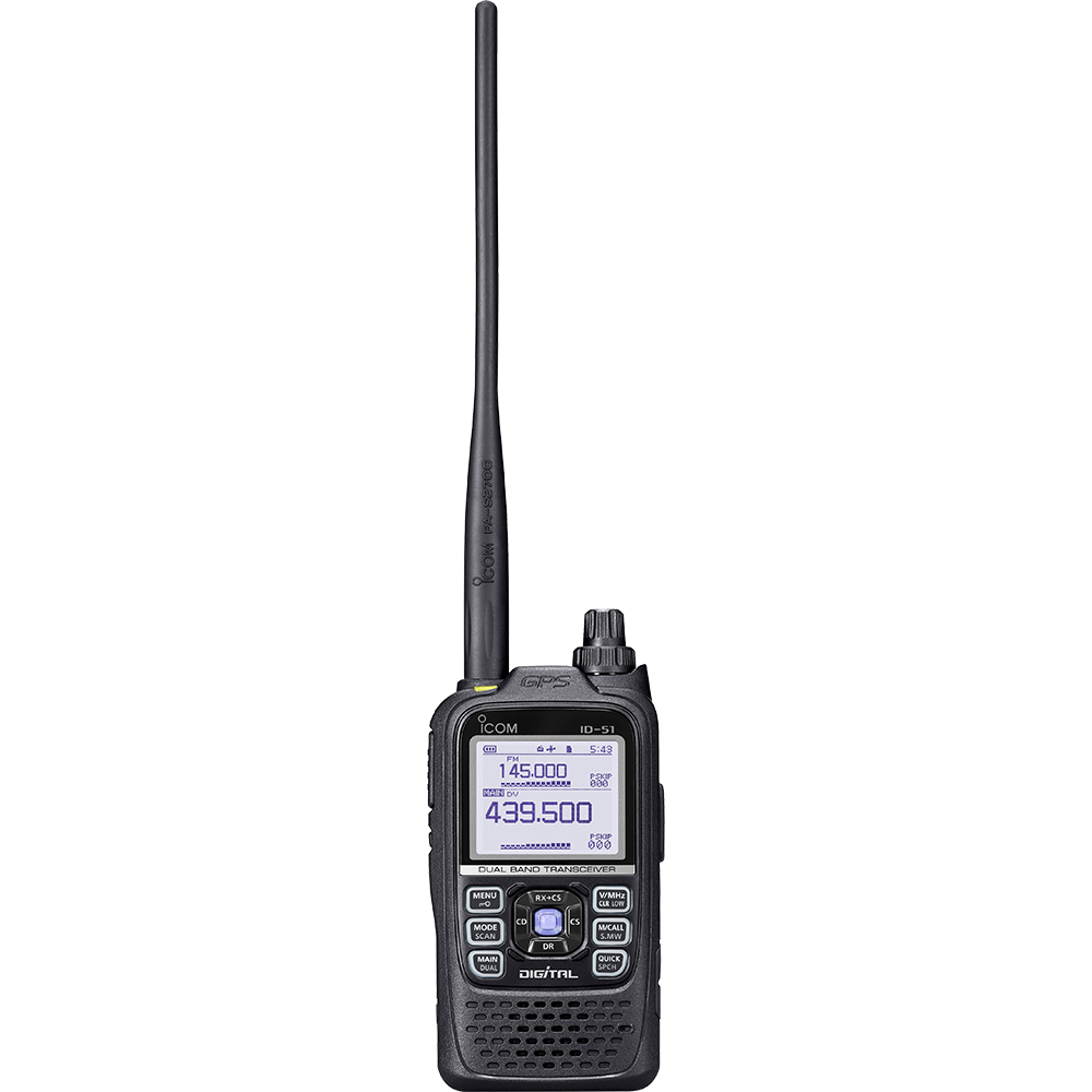
The ID-51E PLUS and the ID-51 of the ICOM handheld are great amateur radios. They offer access to the 2m and 70cm bands with D-STAR capabilities.
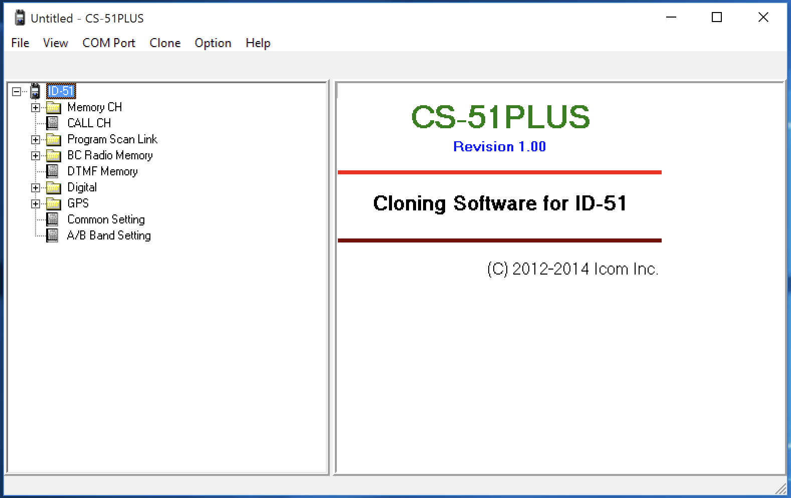
While the radio can be programmed manually via its controls and display, using a computer helps a lot and allows creating backups of the configuration and clone/restore to other radios using the CS-51 PLUS Software from ICOM.
There are a few options to communicate with the radio via cables:
-
OPC-2218LU
-
OPC-2350LU
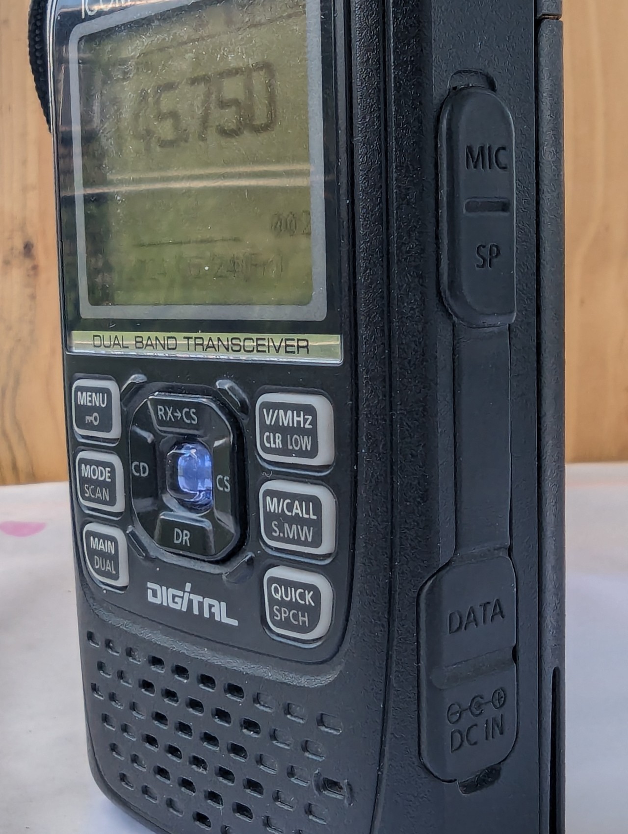
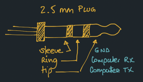
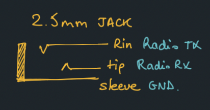
Those cables use the data port via a 2.5mm jack. This port should not be confused with the audio port which is a 2.5mm jack, that also can receive CI-V data as well as audio.
|
Note
|
2.5mm is not your standard headphone jack (which is 3.5mm). The 2.5mm jack is a bit less common but can be found in many devices such as IR remote etc…. As a Ham, you probably already have some laying around. If not, you will have no problem finding one, that will probably be too big… but more on that below. |
2.1. Requirements
Before jumping into the electronics, make sure you have the following tools and parts:
|
Note
|
I went this way because I had the part laying around. You can also use a USB to RS232 adapter directly instead of the 2 last parts. |
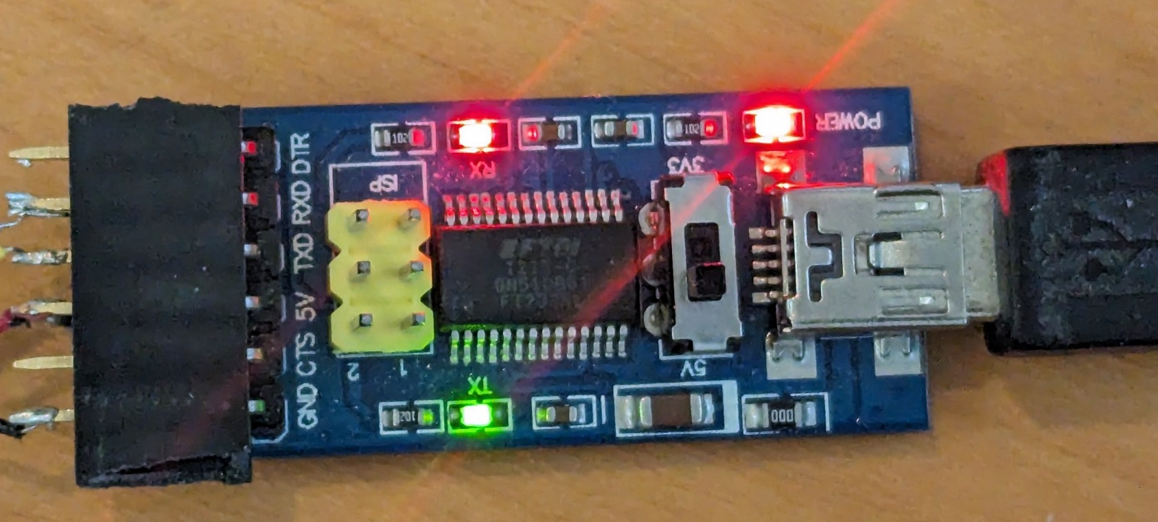
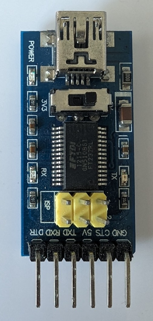
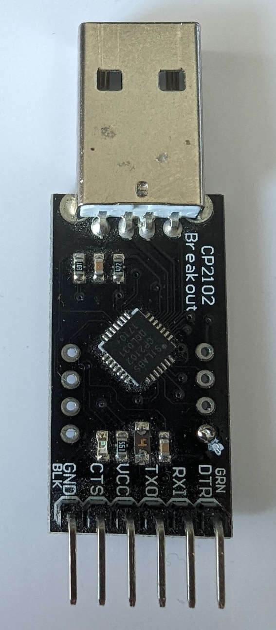
As far as the USB to TTL adapter is concerned, I tested using 2 different ones and both worked just fine. One however was a little more convenient during the debugging phase as it should blink a red led when data was send and blink a green led when data was received. The 2 adapters I used are:
-
a CP2102 based adapter like this one
-
a FTDI based adapter
The main motivation for using one or another is how well it will be supported by your OS. I am using MacOS, some adapters require no drivers, some others require drivers but once installed, it works fine. Some USB/TTL adapters also come with a 3.3V/5V switch which can be useful (not in our case), some offers a RX and a TX LED which can be useful for debugging and visualizing whether you are sending/receiving data.
If you run into issues with those adapters, do check your cables first. I have had countless issues using bad/wrong cables such as cables made for charging only…
-
Soldering iron
-
a voltmeter will help
-
an oscilloscope, while optional, may help debugging if you run into issues
Communication with the Radio via cables does require some settings to be set on the radio itself. More on that below but keep that in mind if your radio plays dead … I am talking from experience here :)
3. The build
I would suggest to progress in your build following the steps below to exclude all the issues I came accross. While skipping some steps may still work in the end, following the steps will help you save time in case something is not working as expected.
3.1. Get the radio to "talk"
One of the issue I ran into is an issue that Florian mentioned in his blog post: the 2.5mm jack. I did not expec any issue with that but I was wrong… My 2.5mm jack was cute and tiny and I really thought it was a good fit… yet it was too big and did not allow proper contact.
It is nearly impossible to check without actually testing the connection so let’s do that first.
We can use CI-V to check that we can receive data from the radio via the data cable. If that test fails, there is no need to go further and the problem needs to be fixed first.
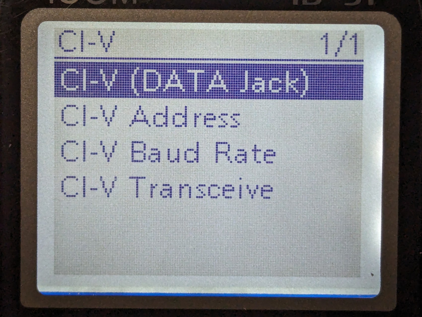
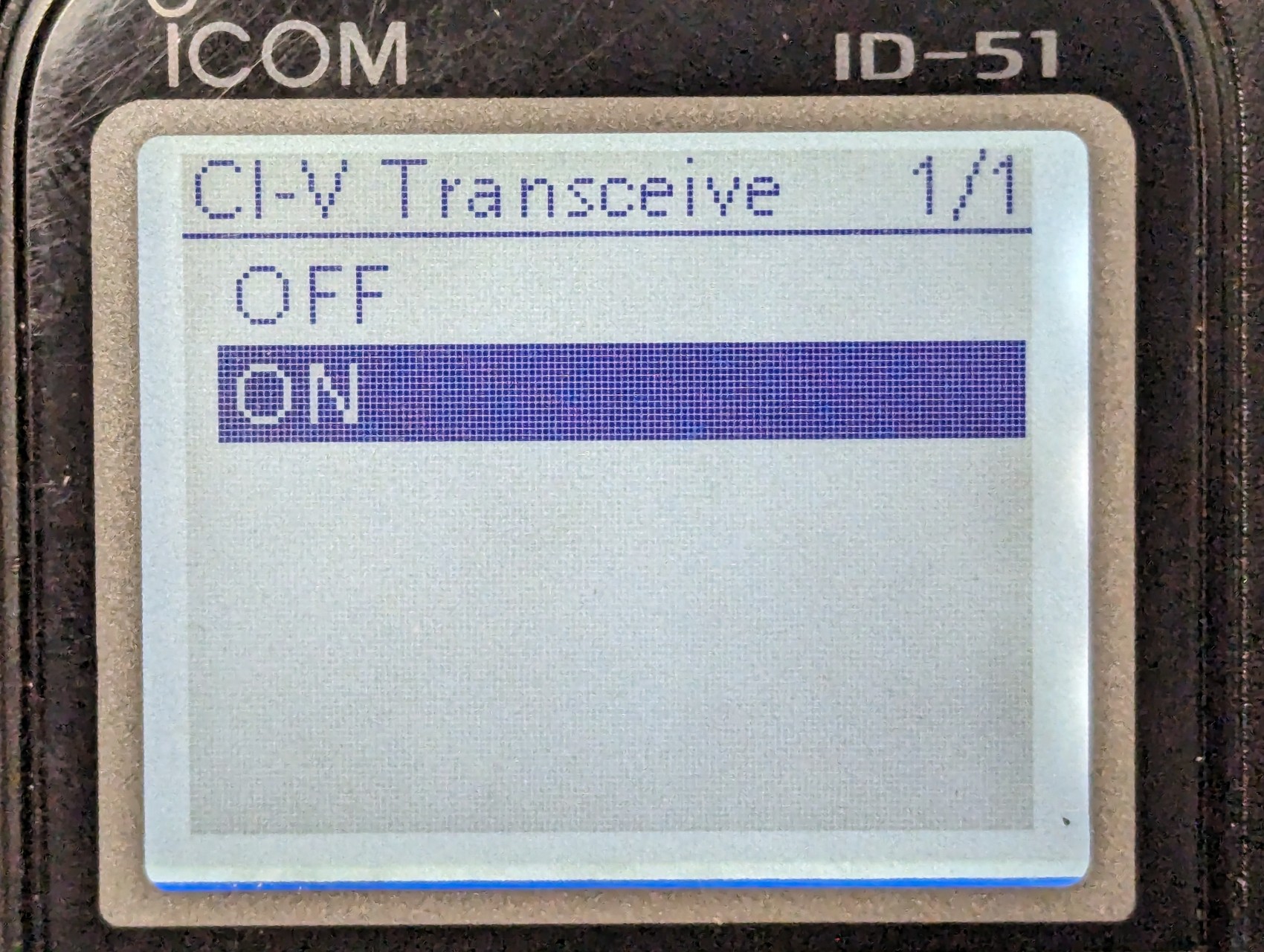
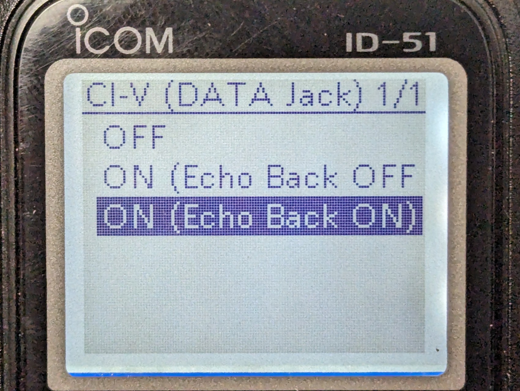
In the ID-51, enable CI-V via data cable in the settings:
-
Menu → functions → CI-V → CI-V (Data JACK) → ON (either one)
-
Menu → functions → CI-V → … other irrelevant entries …
-
Menu → functions → CI-V → CI-V Transceive → ON
We will test in a second but from now on, the radio should be sending CI-V commands via the data cable when you change the frequency for instance. You do not need to transnmit RF for those tests.
3.2. Wiring
First we will test the connection between the radio and the MAX3232. Make sure all the connections are properly soldered and that there is no shorts.
Since the MAX3232 drawws its power from the USB/TTL adapter, make sure you plug this USB/TTL adapter to your computer.
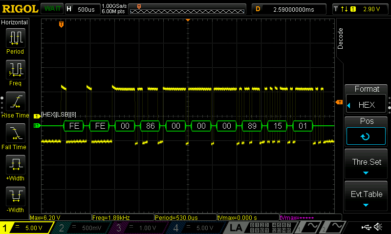
Plug an oscillo or a voltmeter to GND and the cable connected to the RING of the 2.5mm plug. Now, when you change the frequency on the radio, you should see some data coming out of the radio.
If that’s the case, congrats, your connections look good so far.
Notice that we get a RS232 signal from the radio (-5V/+5V). This signal is not TTL (0/+5V). This is an important finding that is confirmed on page 52 of the service manual of the ID-51.
The kudos go to Florian for spotting the J4 connector. The schematics shows the usage of a MAX3221 IC so we know what kind of signal is expected. If you wonder about the voltage limits of the RS232 signal that are acceptable, you may refer to the technical specs of the MAX3221 and you will see that both RIN (±25) and DOUT (±13.2) accept a rather high voltage range.
3.3. Test 2/3: Computer can send data
For this test, the 2.5mm plug does not need to be plugged into the radio. I would even recommend not plugging it so we check what signal we generate before sending it to the radio !
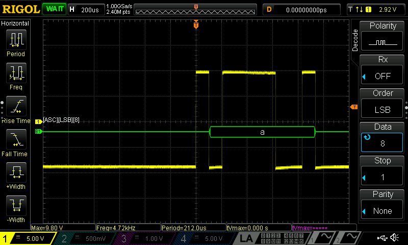
To check whether we are sending data properly, we need to check that: - we do send a TTL signal (0/+~5V) to the MAX3232 - we converts the TTL signal to RS232 (-5V/+5V). We will see that our MAX3232 actually generates a signal that is between -9.80V and +9.80V which is well within the acceptable range of the receiver MAX3221.
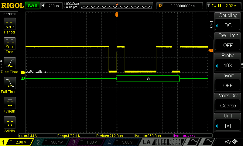
This can be done by probing the GND and TX pins of the USB/TTL adapter.
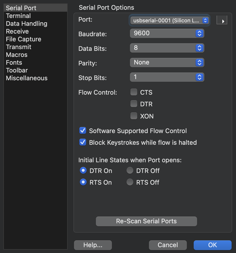
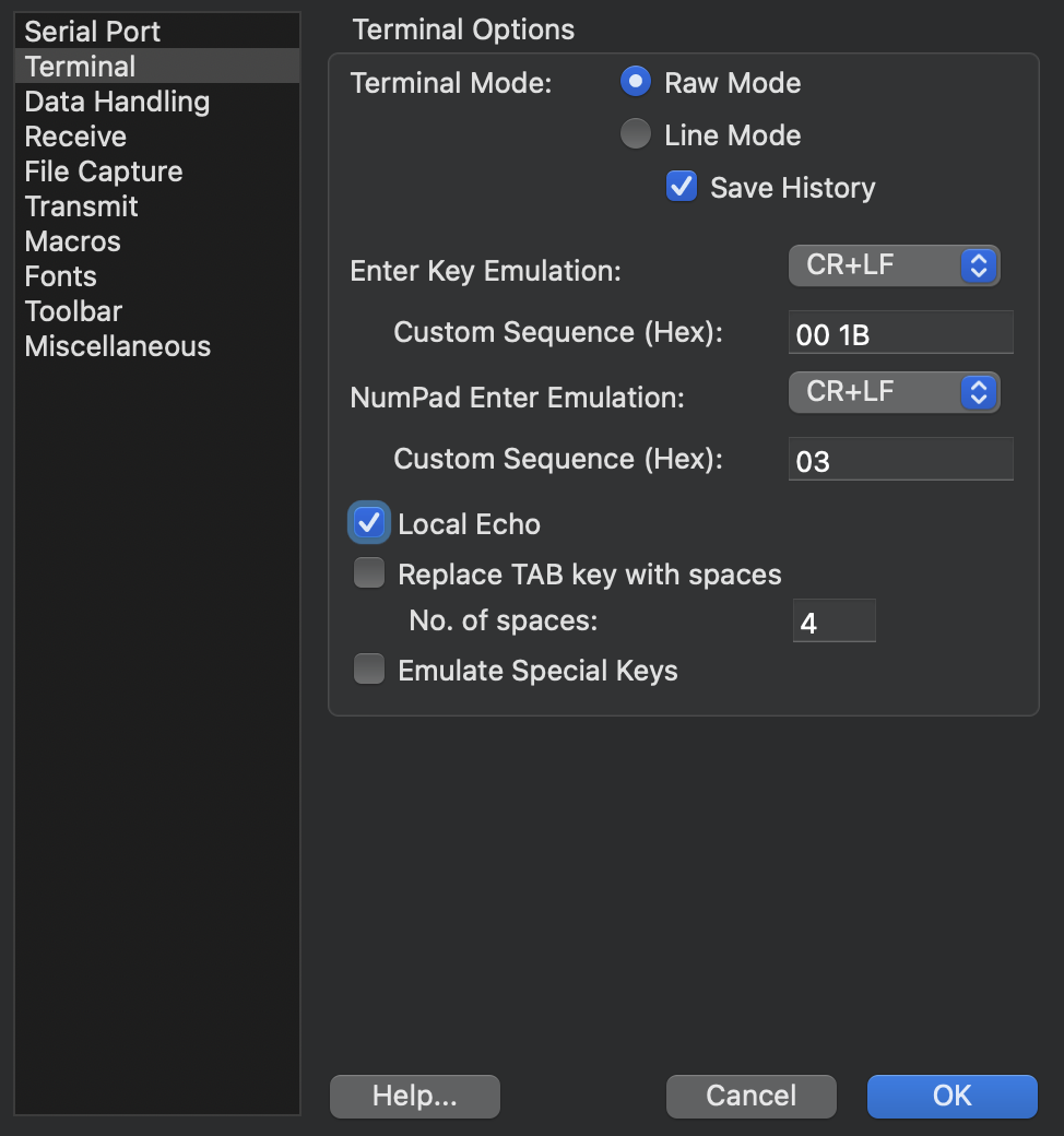
You can use Coolterm on MacOS or some equivalent on Windows. The settings do not matter much so keep it simple with a low Baudrate such as 9600bps for instance. Here are my Cooolterm settings as reference:
As a test, I simply typed the letter 'a' in Coolterm. The TTL signal is a 0/+3.3V signal. This may vary, depending on the USB/TTL adapter you are using.
We get a signal that is between -9.80V and +9.80V. This is well within the acceptable range of the receiver MAX3221. It is good to see that we are still decoding the letter 'a' :)
3.4. Test 3/3: Both RX and TX work
This is our final test. Now we need to insert the plug into the radio (make sure the radio still on …).
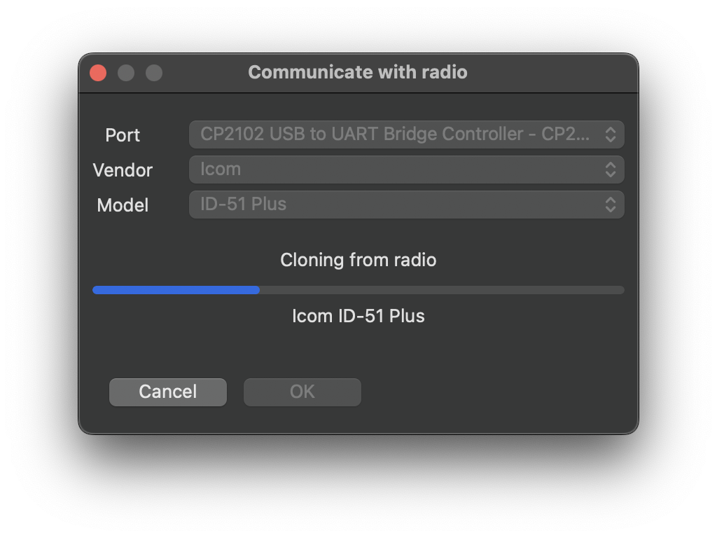
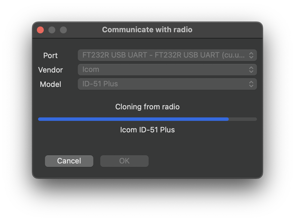
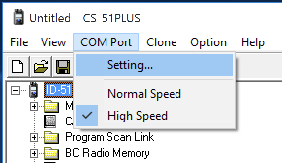
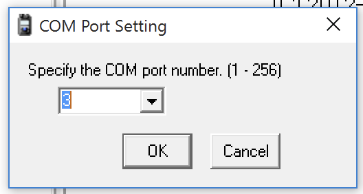
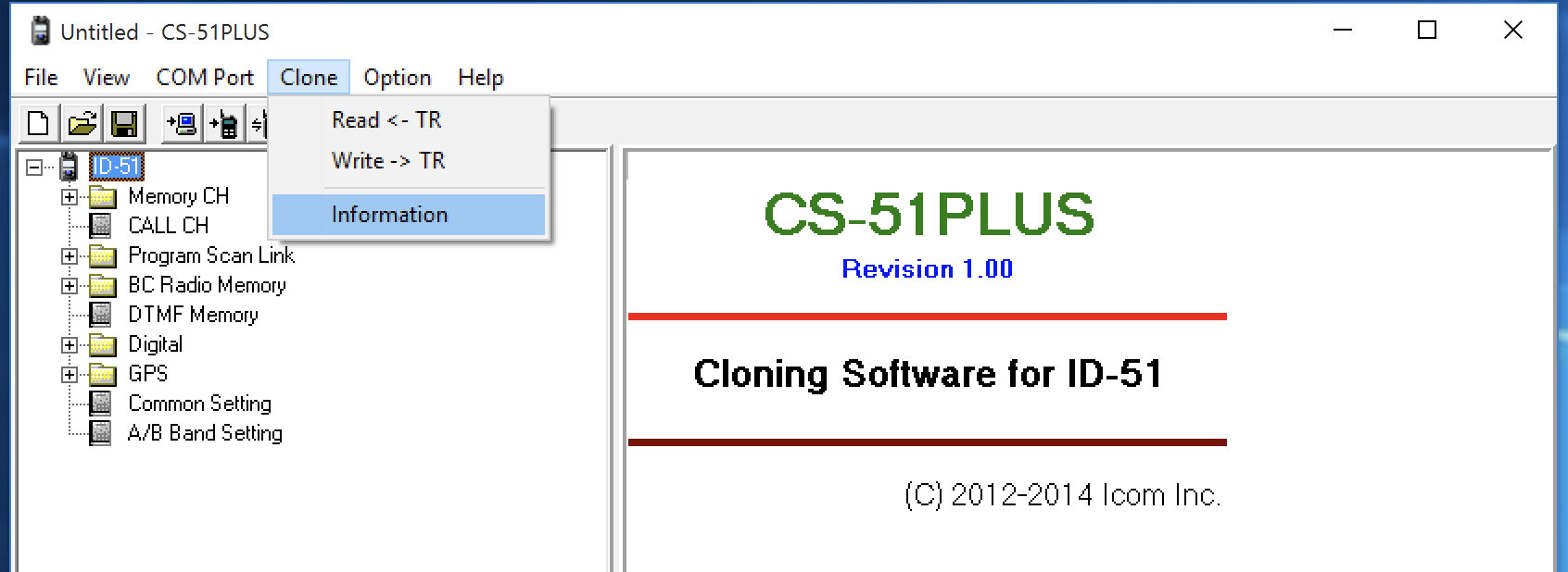
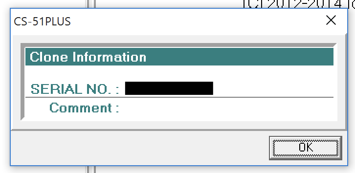
In the CS-51 PLUS software, you can now try to read the radio configuration.
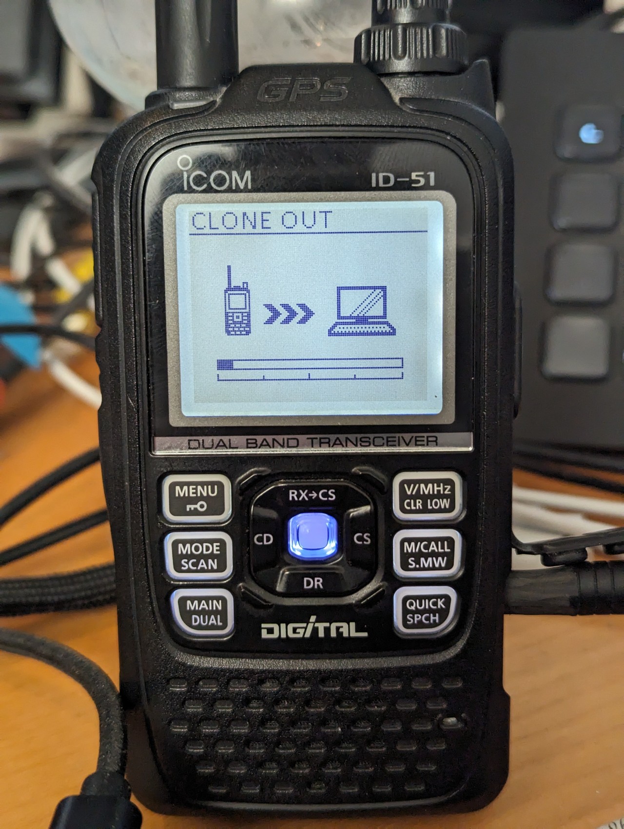
You can now try cloning the radio. It will take a few minutes. After cloning your radio, it will reboot.
4. Wrap-up
We have seen how the cable is made of and what is the "magic" behind it. We have learned how to make the cable and troubleshoot the most common isues.
I can also highly recommend a visit of Florian Wolters (DF2ET)'s blog. He has quite a bunch of interesting posts and experiments.
5. Disclaimers
5.1. Licenses
The following post is about devices that cannot be operated without a proper license. Please make sure you are allowed to use the devices you are building cables for. Check the regulations in your country and make sure you have the proper licenses.
5.2. Links
This post contains referral links to Amazon.
